LED Controller v1.0.0
Introduction
This project was born for two reason:
- to improve my knowledge about the Object-oriented programming in C++;
- to construct a personal LED Controller with control knobs, specifically one for intensity and three for selecting various colors (red, green and blue), for my desk.
Furthermore, I want to share this project and a little guide on how to build it.
What do you need
Firstly, you’ll need these components:
| Qty. | Component |
|---|---|
| 1 | Arduino Nano |
| 1 | SD card reader |
| 1 | MicroSD |
| 1 | LED strip RGB 5050 SMD not addressable at 12V |
| 1 | Led strip connector 4 pin |
| 1 | Led strip extension |
| 1 | Positive Voltage Regulator L7805 |
| 3 | Transistor TIP120 |
| 3 | Resistor at 220Ω |
| 6 | Resistor at 10kΩ |
| 3 | Resistor at 1kΩ |
| 1 | Green LED diode at 5mm |
| 1 | Red LED diode at 5mm |
| 3 | Switch Tact at 6x6x5mm |
| 1 | Switch SPST at 15x10x10mm |
| 4 | Rotary encoder |
| 1 | Female base for Power supply |
| 1 | Power supply at 2A, 12V |
| undef. | Wires both for 2A and 100mA of electrical current |
The size of microSD is not important because each file will be 1 kb. In the SD there will be four files, that is the three profile and the manual configuration to load on every power up. This lists are merely indicative, but the size and the type of component are correct. In addition, if you want to realized the PCB at home, consider to use these other materials:
| Qty. | Component |
|---|---|
| 2 | Copper clad board double-sided |
| 1 | Copper clad board single-sided |
| undef. | Rivet at 1x2.5mm |
Consider the external diameter of rivet and in this case modify the files of PCBs. Currently, the diameter is 1mm.
I don’t suggest you the type and the color of filament for the case. My chose has been the black color on PLA filament; same material for the buttons but in grey color.
Realizing the PCB
There are two ways to realize the PCB:
- by taking advantage with some company that realize it cheaply;
- by you with several techniques.
In my case I decided to realize the circuit board at home. The first idea was to use a stripboard, but the realization of the tracks would be little elegant for the final result, considering the number of the components and its connections.
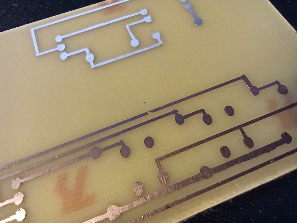
I decided to draw the tracks and holes on the circuit board with my 3D printer (like a plotter),
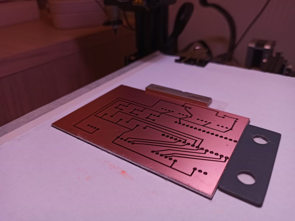
immersing it in ferric chloride solution,
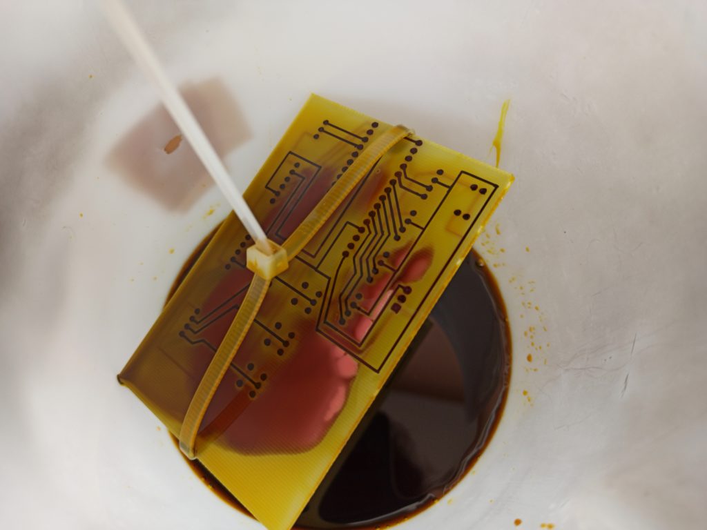
and then cleaning it with 99% isopropyl alcohol.
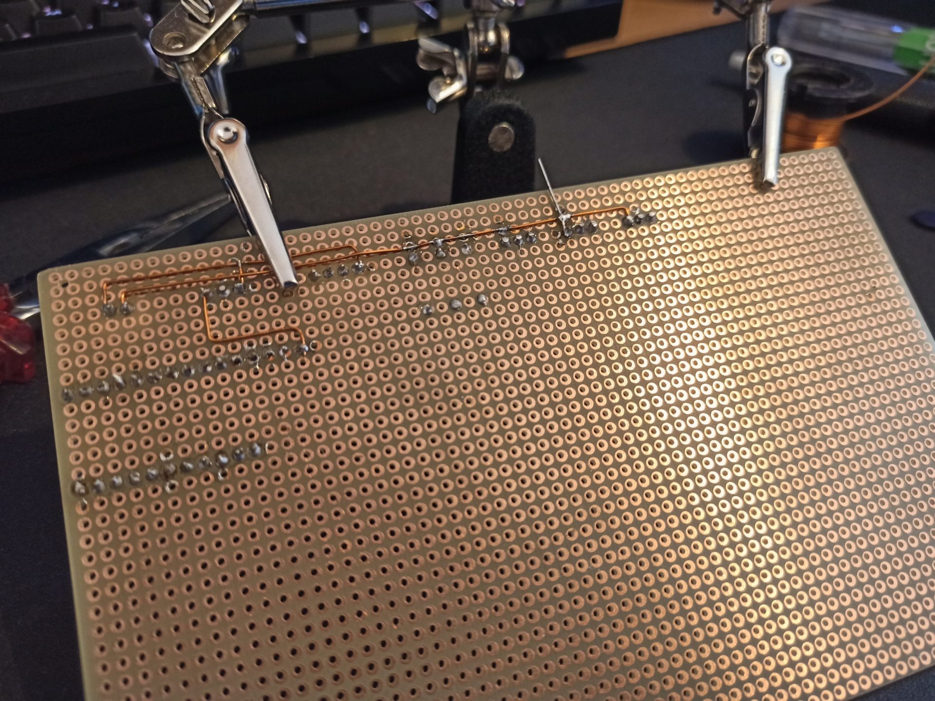
The only flaw is the interruption of some track. I don’t know if is due from the permanent maker, in this case the Sharpie Ultra Fine Point. Next time I will be allowed to try with another maker, like the Lumocolor as suggested from some friend. To solve it, I soldered a piece of copper wire.
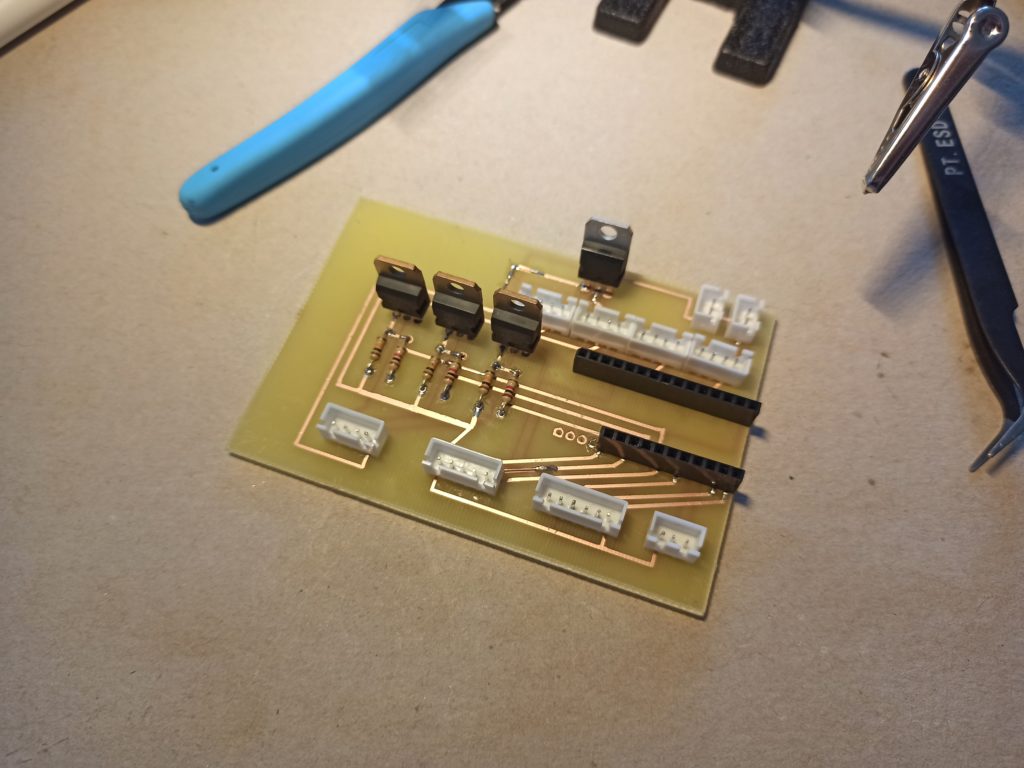
After the realization of the holes with a drill press, applying the rivets and solded the components, the result is realy good. The only precaution has been the distance between the hole track and the rivet, where was not guaranteed the contact. To solve it, I soldered a bit of tin.
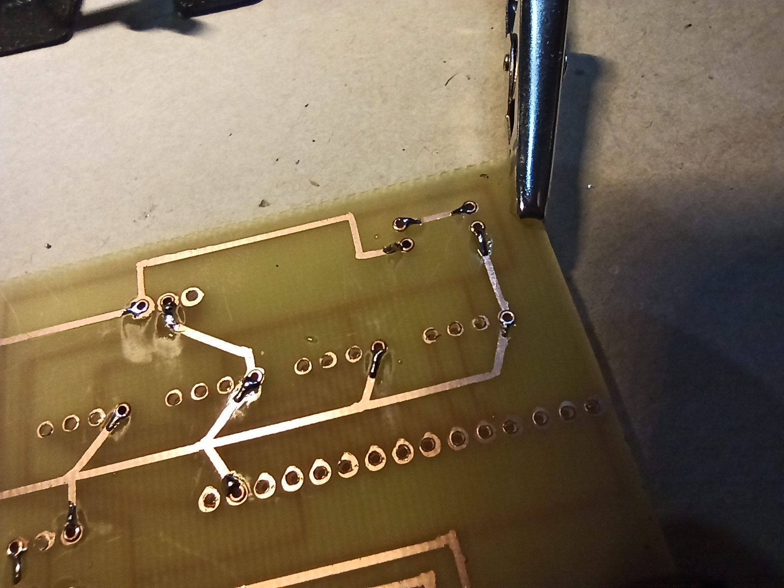
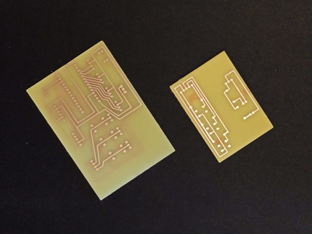
Then, the final result of PCB.
Being an homemade circuit board, I did not marked the names of the connections. To help you, see the files that I share later in this chapter.
Probably you’ll wonder how I used a 3D printer like plotter and how I used a ferric chloride solution. I suggest you to follow this two little guides, customizing the tool for the permanent maker:
Here the files about the PCB. If you want, you will be able to modify them.
| Name | Type | Size |
|---|---|---|
| Mainboard | .fzz | 48,8 kB |
| LED indicators | .fzz | 4,8 kB |
| Profile buttons | .fzz | 9,4 kB |
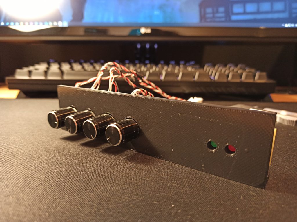
Realizing the case
After the construction of circuit board, you will need a case. Foreword, I’m not a 3D modeling designer but I have realized one. I decided to print it with PLA filament: black color for the base, front and top panel; grey color for the buttons; transparent color for the LED covers. The first print has been the base. For spacing the SD card reader from the base I used four M2x15mm spacers; instead, for the main circuit board I used four M2x3mm spacers.
The second print has been the front panel. For each rotary encoder I used two M3x6mm screws. Instead, for spacing the the LED indicators board from the front panel I used two Dist M2x8mm spacers.
The third print has been the top panel, the three buttons and the two LED covers. Here too I used two M2x5mm spacers.
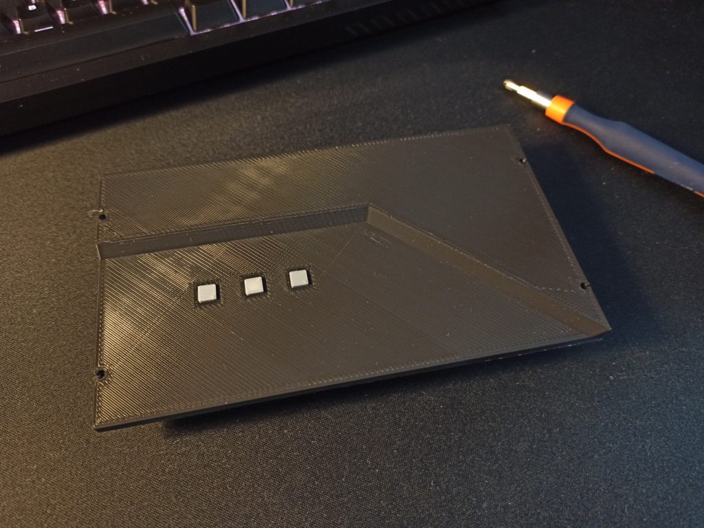
Finally, to mount the top panel at the base I used three M2x10mm screws and one M2x7mm screw.
Finally, to mount the top panel at the base I used three M2x10mm screws and one M2x7mm screw.
Here the files about the case. If you want, you will be able to modify them.
| Name | Type | Size |
|---|---|---|
| Base | .stl | 88,4 kB |
| Front panel | .stl | 167 kB |
| Top panel | .stl | 65,8 kB |
| Button | .stl | 1,4 kB |
| LED cover | .stl | 31,9 kB |
| Project | .f3d | 450 kB |
Installing the software
Finally, the last chapter about the realitazion of this project. Actually, this was the first thing that I did, infact on the basis of this, I realized the circuit board (with a breadboard) and the case for it.
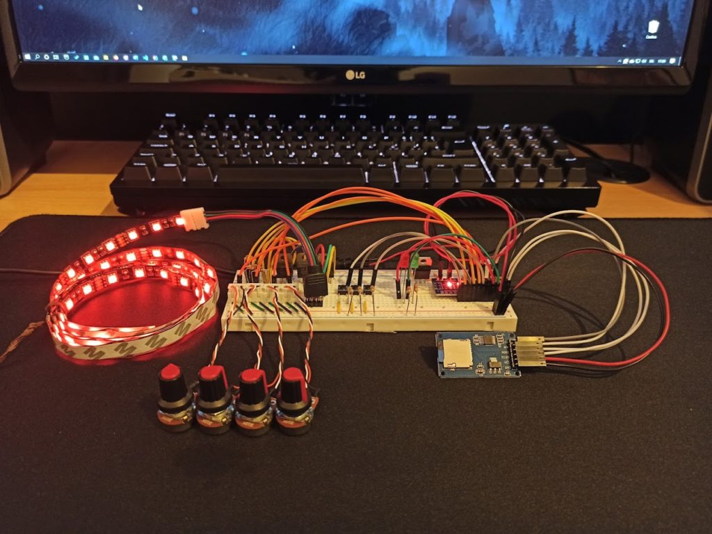
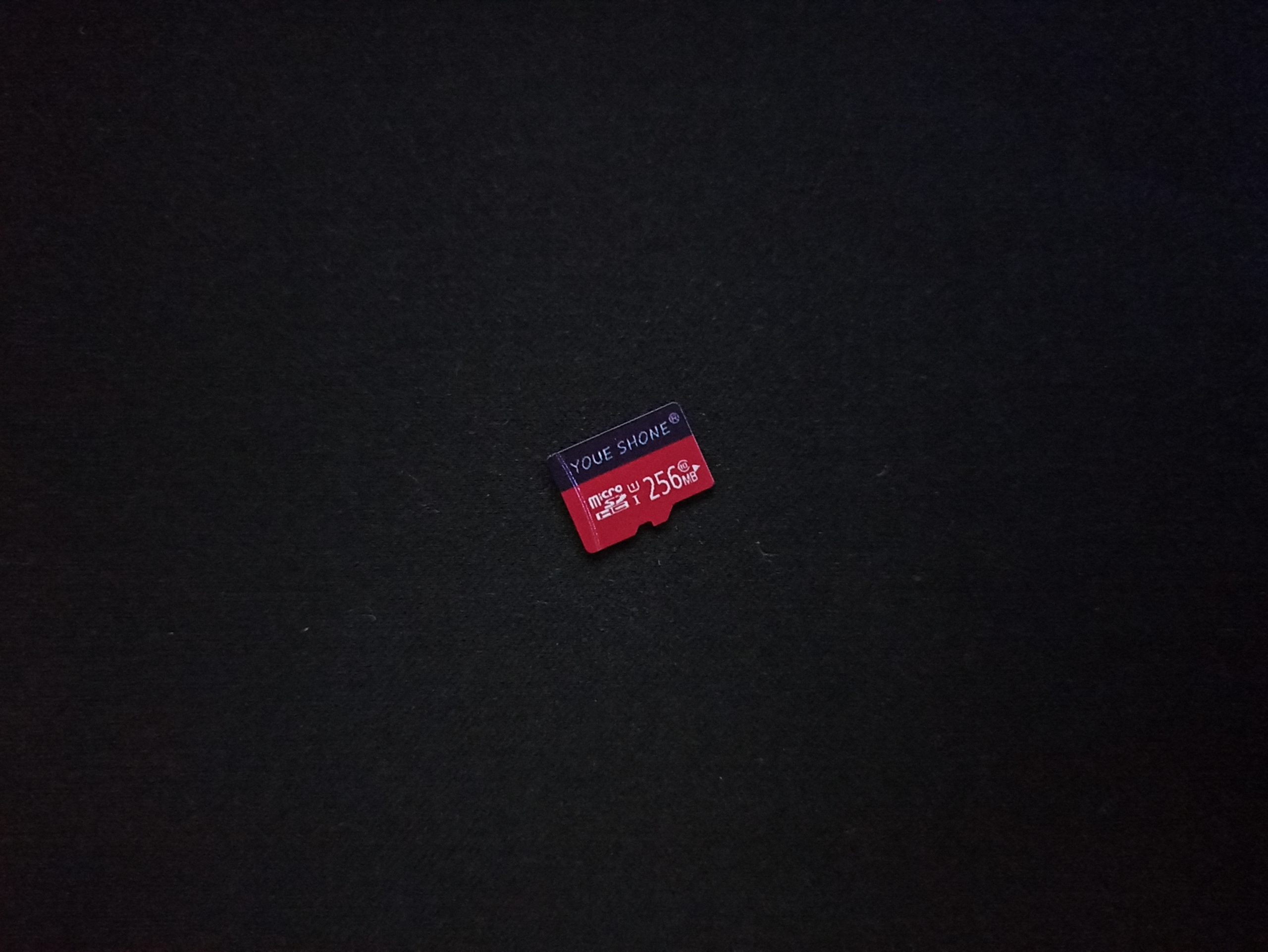
As you will see in this image, I used the potentiometers until a dear friend suggested me the rotary encoder. This component has simplified the code significantly. For saving the files of profiles I used this disgusting 256 MB microSD card. “Disgusting” because I have been several hour to understand the reason of corruption of files.
For realizing the code of this project I used PlatformIO on Visual Studio Code. As I said in before, this project borns for two reason. Thanks to it, I have realized two main libraries available on official Library Manager of Arduino:
- Button-Arduino, to manage the button with short and long press;
- AnalogIO-Arduino, to manage the analog input/output.
Here the files about the software.
| Name | Type | Size |
|---|---|---|
| LED Controller v1.0.0 | .zip | 86,7 kB |
I suggest you to use PlatformIO, importing the folder like a project and then writing the software on your microcontroller, that will has to be an Arduino Nano. If you want, you can change it with another microcontroller, considering to modify the circuit board, the case and the file config.h in src folder.
1 | /* Setting the input and output pins about the encoders and the strip led, and the speeds for the encoders */ |
My wish is the names of variable are documented themself.
Conclusion
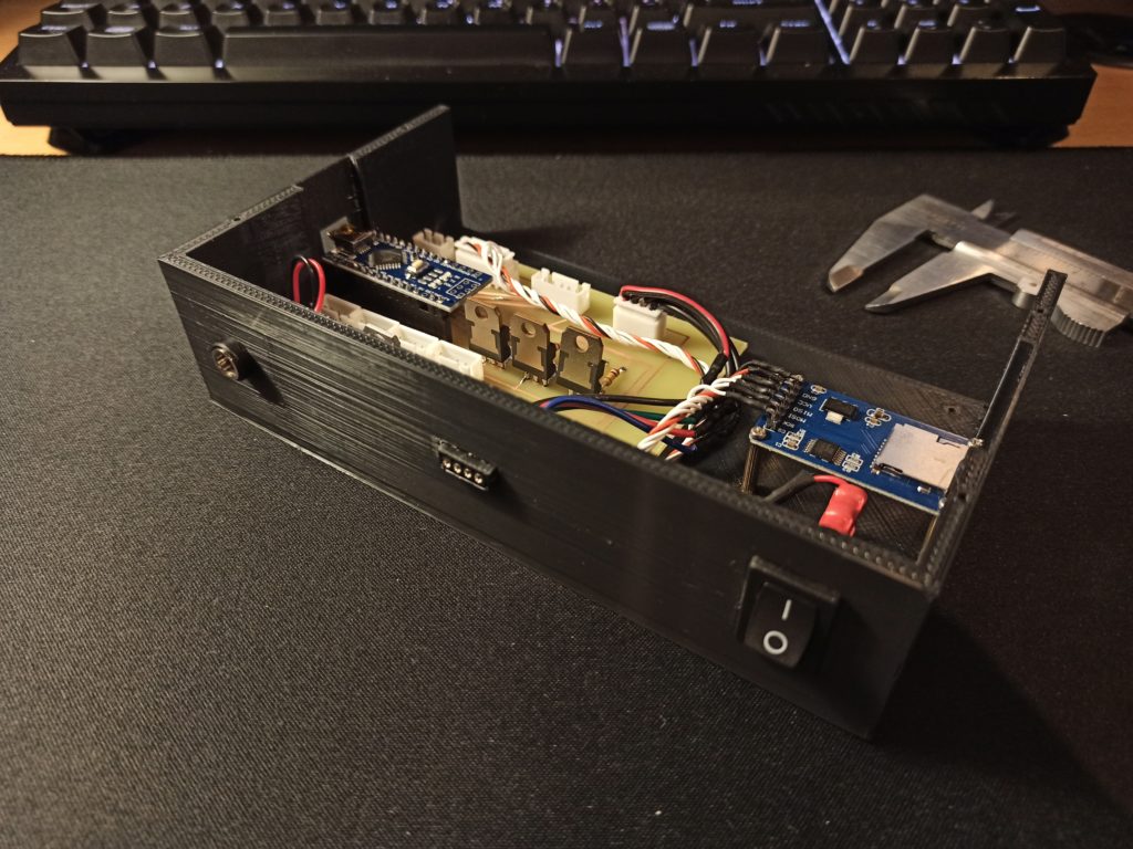
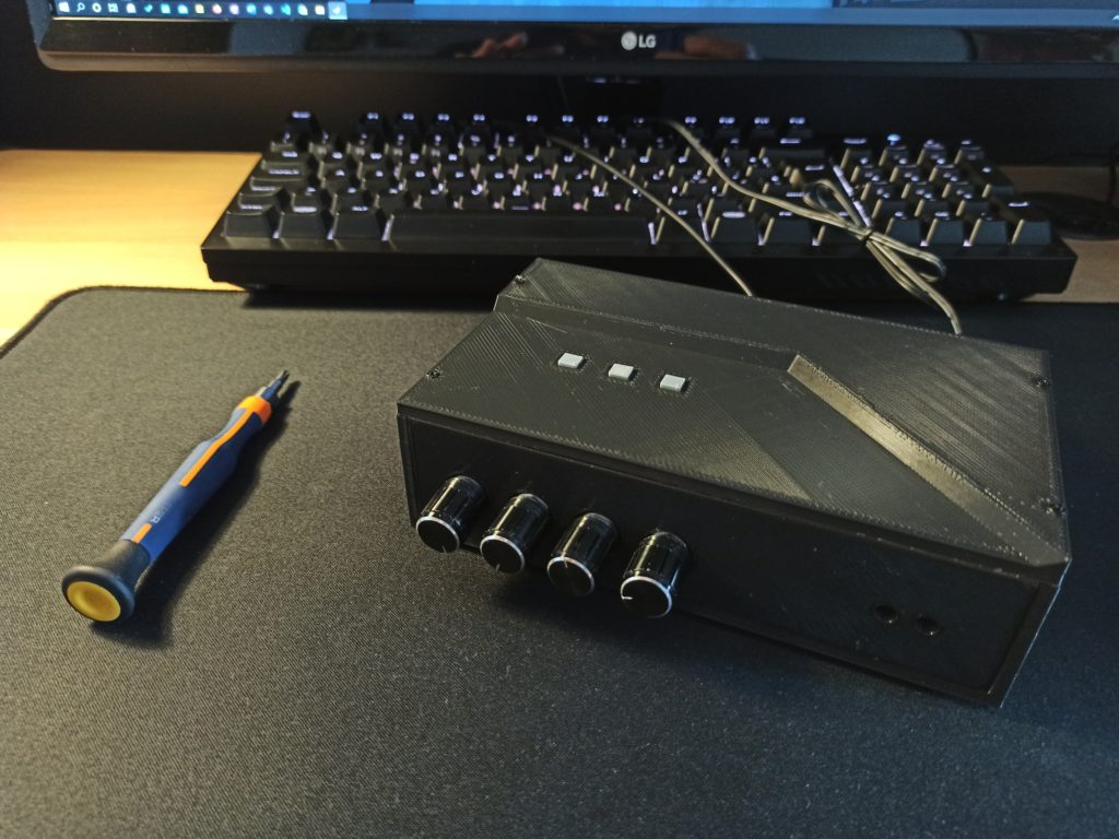
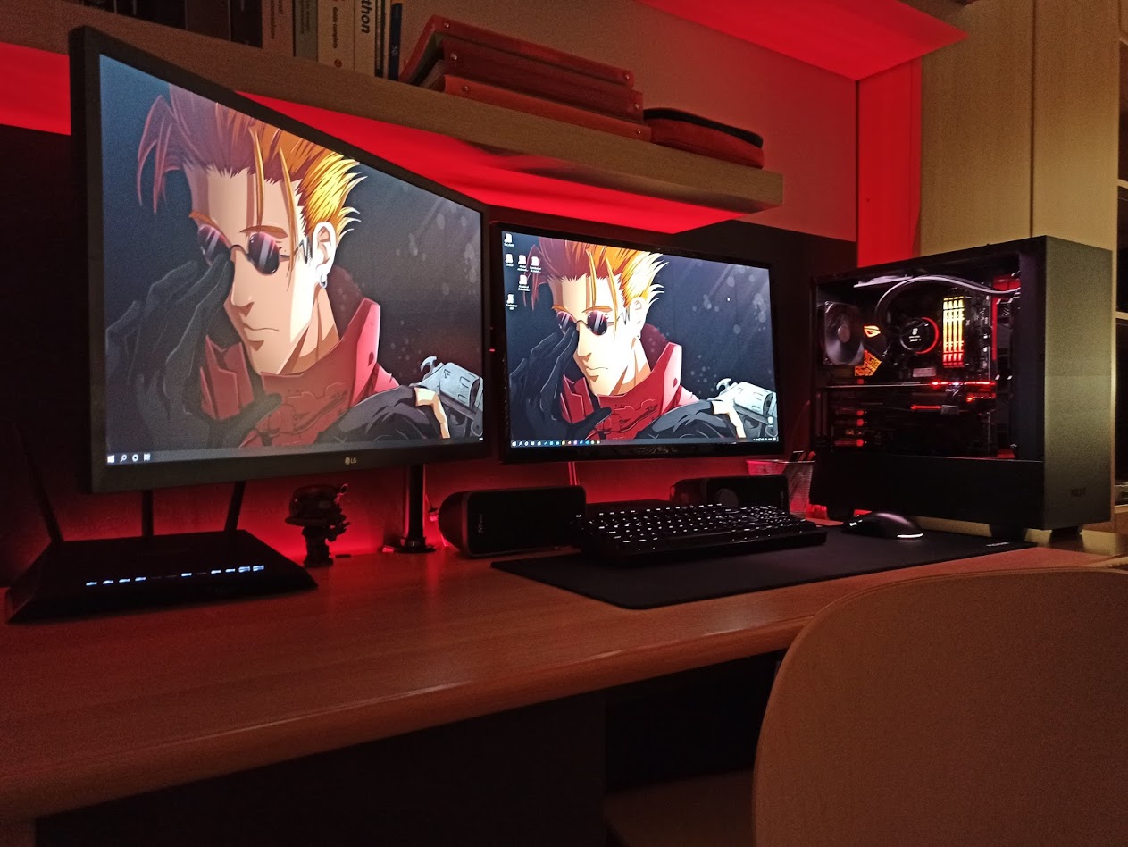
With this image you can see the final result on my desktop.
In this project I have certainly learned the Object-oriented programming, but I have not followed one of the enginnering principles: the anticipation of change. Infact, few week later was born the necessity to manage the LED Controller with my smartphone. Do to this, the microcontroller will has to change with an ESP8266 or ESP32, that is a microcontroller with Wi-Fi. Infact, the next version will have this feature, with an OLED screen to view the values of the configuration and the profile loaded at the moment. This implies to change the PCB and the case.
Thank you for reading this article and if you have some suggestion, write me at davidepalladino@hotmail.com.